- 您现在的位置:买卖IC网 > Sheet目录867 > LSM2-T/16-D12N-C (Murata Power Solutions Inc)CONV DC/DC 80W 16A 12V SMD
�� �
�
�LSM2� Series�
�Single� Output,� Non-Isolated�
�Selectable-Output� POL� DC/DC� Converters�
�The� remote� sense� line� is� part� of� the� feedback� control� loop� regulating�
�the� DC/DC� converter’s� output.� The� sense� line� carries� very� little� current� and�
�consequently� requires� a� minimal� cross-sectional-area� conductor.� As� such,�
�it� is� not� a� low-impedance� point� and� must� be� treated� with� care� in� layout� and�
�cabling.� Sense� lines� should� be� run� adjacent� to� signals� (preferably� ground),� and�
�in� cable� and/or� discrete-wiring� applications,� twisted-pair� or� similar� techniques�
�should� be� used.� To� prevent� high� frequency� voltage� differences� between� V� OUT�
�and� Sense,� we� recommend� installation� of� a� 1000pF� capacitor� close� to� the�
�converter.�
�The� sense� function� is� capable� of� compensating� for� voltage� drops� between�
�the� +Output� and� +Sense� pins� that� do� not� exceed� 10%� of� V� OUT� .�
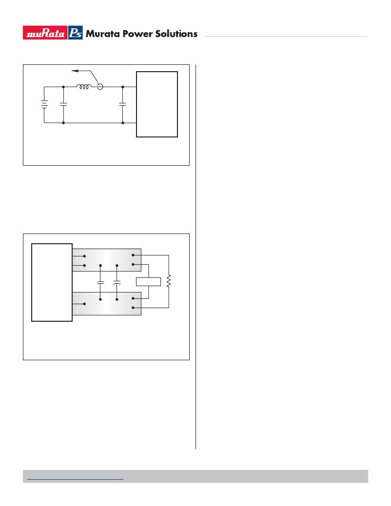
�Figure� 2.� Measuring� Input� Ripple� Current�
�Start-Up� Time�
�The� V� IN� to� V� OUT� Start-Up� Time� is� the� interval� between� the� time� at� which� a� ramp-�
�ing� input� voltage� crosses� the� lower� limit� of� the� speci?ed� input� voltage� range�
�and� the� fully� loaded� output� voltage� enters� and� remains� within� its� speci?ed�
�accuracy� band.� Actual� measured� times� will� vary� with� input� source� impedance,�
�external� input� capacitance,� and� the� slew� rate� and� ?nal� value� of� the� input� volt-�
�age� as� it� appears� to� the� converter.�
�[V� OUT� (+)� –� Common]� –� [Sense(+)� –� Common]� ?� 10%V� OUT�
�Power� derating� (output� current� limiting)� is� based� upon� maximum� output� cur-�
�rent� and� voltage� at� the� converter’s� output� pins.� Use� of� trim� and� sense� functions�
�can� cause� the� output� voltage� to� increase,� thereby� increasing� output� power�
�beyond� the� LSM2's� speci?ed� rating.� Therefore:�
�(V� OUT� at� pins)� x� (I� OUT� )� ?� rated� output� power�
�The� internal� 10.5� ??� resistor� between� +Sense� and� +Output� (see� Figure� 1)�
�serves� to� protect� the� sense� function� by� limiting� the� output� current� ?owing�
�through� the� sense� line� if� the� main� output� is� disconnected.� It� also� prevents�
�output� voltage� runaway� if� the� sense� connection� is� disconnected.�
�Note:� If� the� sense� function� is� not� used� for� remote� regulation,� +Sense� must�
�+SENSE�
�+OUTPUT�
�6�
�4�
�COPPER� STRIP�
�be� tied� to� +Output� at� the� DC/DC� converter� pins.�
�Sense� Input�
�Use� the� Sense� input� with� caution.� Many� applications� do� not� need� the� Sense�
�C1�
�C2�
�SCOPE�
�R� LOAD�
�connection.� Sense� is� intended� to� correct� small� output� accuracy� errors� caused�
�by� the� resistive� ohmic� drop� in� output� wiring� as� output� current� increases.� This�
�output� drop� (the� difference� between� Sense� and� V� OUT� when� measured� at� the�
�COMMON�
�3�
�COPPER� STRIP�
�converter)� should� not� be� allowed� to� exceed� 0.5V.� Consider� using� heavier� wire� if�
�this� drop� is� excessive.�
�Sense� is� connected� at� the� load� and� corrects� for� resistive� errors� only.� Be�
�C1� =� NA�
�C2� =� 22μF� TANTALUM�
�LOAD� 2-3� INCHES� (51-76mm)� FROM� MODULE�
�Figure� 3.� Measuring� Output� Ripple/Noise� (PARD)�
�careful� where� it� is� connected.� Any� long,� distributed� wiring� and/or� signi?cant�
�inductance� introduced� into� the� Sense� control� loop� can� adversely� affect� overall�
�system� stability.� If� in� doubt,� test� the� application,� and� observe� the� DC/DC's� output�
�transient� response� during� step� loads.� There� should� be� no� appreciable� ringing� or�
�oscillation.� You� may� also� adjust� the� output� trim� slightly� to� compensate� for� voltage�
�loss� in� any� external� ?lter� elements.� Do� not� exceed� maximum� power� ratings.�
�The� On/Off� to� V� OUT� Start-Up� Time� assumes� the� converter� is� turned� off� via� the�
�On/Off� Control� with� the� nominal� input� voltage� already� applied� to� the� converter.�
�The� speci?cation� de?nes� the� interval� between� the� time� at� which� the� converter�
�is� turned� on� and� the� fully� loaded� output� voltage� enters� and� remains� within� its�
�speci?ed� accuracy� band.� See� Typical� Performance� Curves.�
�Remote� Sense�
�LSM2� Series� offer� an� output� sense� function.� The� sense� function� enables�
�point-of-use� regulation� for� overcoming� moderate� IR� drops� in� conductors� and/or�
�cabling.� Since� these� are� non-isolated� devices� whose� inputs� and� outputs� usually�
�On/Off� Control�
�The� On/Off� Control� pin� may� be� used� for� remote� on/off� operation.� LSM2� Series�
�DC/DC� converters� are� designed� so� that� they� are� enabled� when� the� control� pin�
�is� left� open� (open� collector).�
�Dynamic� control� of� the� on/off� function� is� best� accomplished� with� a� me-�
�chanical� relay� or� open-collector/open-drain� drive� circuit� (optically� isolated� if�
�appropriate).� The� drive� circuit� should� be� able� to� sink� appropriate� current� when�
�activated� and� withstand� appropriate� voltage� when� deactivated.�
�share� the� same� ground� plane,� sense� is� provided� only� for� the� +Output.�
�www.murata-ps.com/support�
�M� D� C_LSM2� Series.C01� Δ� Page� 5� of� 17�
�发布紧急采购,3分钟左右您将得到回复。
相关PDF资料
LSM2-T/30-D12R-C
CONV DC/DC 125W 30A 12V SMD
LSN-T/10-D12N-C
CONV DC/DC 10A 0.75-5.25V SIP
LSN-T/16-D12-C
CONV DC/DC 80W 16A 0.75-5V SIP
LSN-T/16-W3-C
CONV DC/DC 16A .75-3.3V SIP
LSN2-T/16-W3N-C
CONV DC/DC 52.8W 16A.75-3.3V SIP
LSN2-T/30-D12-C
CONV DC/DC 150W 30A 0.8-5V SIP
LSS-T/10-W12-C
CONV DC/DC 60W 10A .6-6V SIP
LTM4600HVIV#PBF
IC DC/DC UMODULE 10A 104-LGA
相关代理商/技术参数
LSM2-T/16-D12N-C
制造商:Murata Power Solutions 功能描述:DC/DC Converter
LSM2-T/16-D12NG
制造商:Murata Power Solutions 功能描述:Module DC-DC 1-OUT 0.75V to 5V 16A 80W 8-Pin Case C62
LSM2-T/16-D12NG-C
功能描述:DC/DC转换器 52.8W SINGLE OUTPUT 12V / 0.75-5V16A RoHS:否 制造商:Murata 产品: 输出功率: 输入电压范围:3.6 V to 5.5 V 输入电压(标称): 输出端数量:1 输出电压(通道 1):3.3 V 输出电流(通道 1):600 mA 输出电压(通道 2): 输出电流(通道 2): 安装风格:SMD/SMT 封装 / 箱体尺寸:
LSM2-T/16-W3
制造商:Murata Power Solutions 功能描述:Module DC-DC 1-OUT 0.75V to 3.3V 16A 52.8W 8-Pin Case 62
LSM2-T/16-W3-C
功能描述:DC/DC转换器 52.8W SINGLE OUTPUT 5V / 0.75-3.3V16A
RoHS:否 制造商:Murata 产品: 输出功率: 输入电压范围:3.6 V to 5.5 V 输入电压(标称): 输出端数量:1 输出电压(通道 1):3.3 V 输出电流(通道 1):600 mA 输出电压(通道 2): 输出电流(通道 2): 安装风格:SMD/SMT 封装 / 箱体尺寸:
LSM2-T/16-W3G
制造商:Murata Power Solutions 功能描述:Module DC-DC 1-OUT 0.75V to 3.3V 16A 52.8W 8-Pin Case C62
LSM2-T/16-W3G-C
功能描述:DC/DC转换器 52.8W SINGLE OUTPUT 5V / 0.75-3.3V16A RoHS:否 制造商:Murata 产品: 输出功率: 输入电压范围:3.6 V to 5.5 V 输入电压(标称): 输出端数量:1 输出电压(通道 1):3.3 V 输出电流(通道 1):600 mA 输出电压(通道 2): 输出电流(通道 2): 安装风格:SMD/SMT 封装 / 箱体尺寸:
LSM2-T/16-W3N
制造商:Murata Power Solutions 功能描述:Module DC-DC 1-OUT 0.75V to 3.3V 16A 52.8W 8-Pin Case C62